Home

ιστός επίπεδο Συντομογραφία decoder flip flop Δηλωτικό Ουσιαστικά Κύκλωπας

State Machines - Practical EE

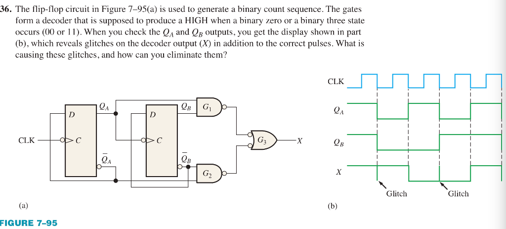
Solved The flip-flop circuit in Figure 7–95(a) is used to | Chegg.com

How to design 4-bit memory using D flip flop - Quora

ECE241F - Digital Systems - Lab #4

How a line decoder works

Modified scan flip-flop to implement RAS. | Download Scientific Diagram

Figure 10 from An ultra-low power wake up receiver with flip flops based  address decoder | Semantic Scholar
Figure 10 from An ultra-low power wake up receiver with flip flops based address decoder | Semantic Scholar
a) Logic map showing the relationship between the FSTD states and... |  Download Scientific Diagram
a) Logic map showing the relationship between the FSTD states and... | Download Scientific Diagram

Accurate Quadrature Encoder Decoding Using Programmable Logic | Semantic  Scholar
Accurate Quadrature Encoder Decoding Using Programmable Logic | Semantic Scholar

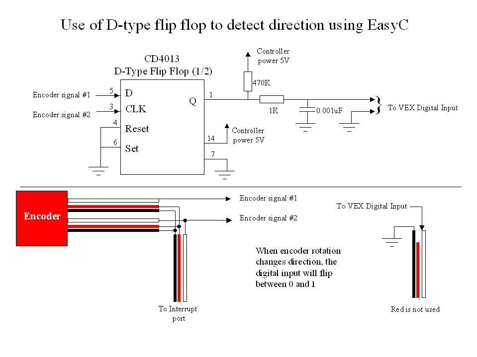
How to detect direction with encoder using EasyC - Technical Discussion -  VEX Forum
How to detect direction with encoder using EasyC - Technical Discussion - VEX Forum

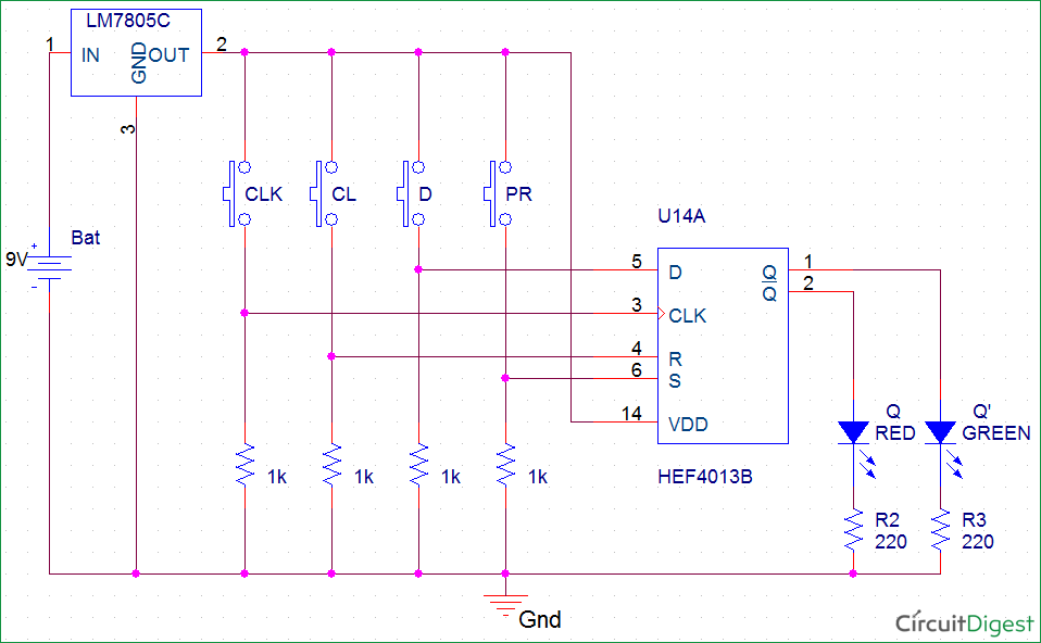
D Flip-Flop Circuit Diagram: Working & Truth Table Explained

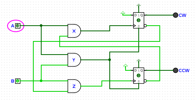
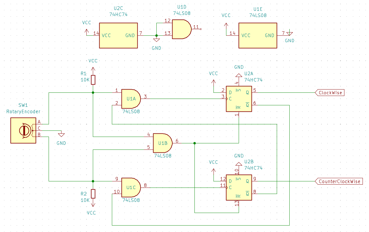
Rotary Encoder Hardware Decoder – cwispy

In-Class Exercise
In-Class Exercise

Rotary Encoder Hardware Decoder – cwispy

4 bit JK Counter w/ BCD decoder - Multisim Live

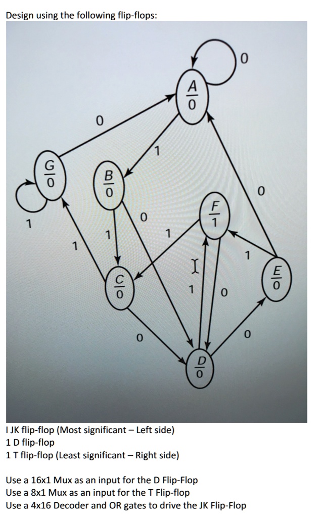
SOLVED: Design using the following flip-flops: 0 G 10 B 10 0 1 0 1 1 1 1 0  0 0 I. JK flip-flop (Most significant - Left side) II. D flip-flop
SOLVED: Design using the following flip-flops: 0 G 10 B 10 0 1 0 1 1 1 1 0 0 0 I. JK flip-flop (Most significant - Left side) II. D flip-flop
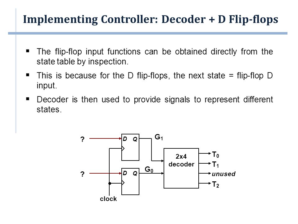
Implementing the Controller. Outline  Implementing the Controller  With  JK Flip-flops  Decoder + D flip-flops  One Flip-flop per State   Multiplexers. - ppt download
Implementing the Controller. Outline  Implementing the Controller  With JK Flip-flops  Decoder + D flip-flops  One Flip-flop per State  Multiplexers. - ppt download

Solved The flip-flop circuit in Figure(a) is used to | Chegg.com

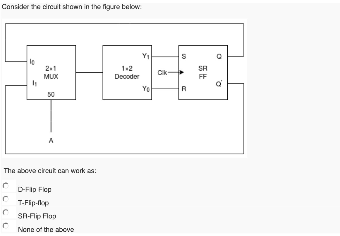
Solved Consider the circuit shown in the figure below: S lo | Chegg.com

MULTIPLEXER, DECODER, FLIP-FLOP, dan COUNTER

EDGE TRIGGERED D FLIP FLOP – CODE STALL

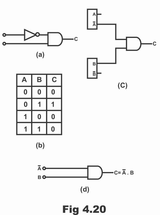
Decoder logic circuit diagram and operation - Electronic Clinic

Edge-triggered D flip-flop behavior